1.1 Introduction & Specifications
-
The Smart Pi One uses the Allwinner H3 Soc. It integrates Ethernet, IR receiver, video/audio output and supports HDMI and AVOUT. It can be powered via the MicroUSB port (DC 5V/2A and POWER DELIVERY CHARGER).
-
In such a small board it still integrates rich interfaces and ports. HDMI, Ethernet, USB-Host, USB-OTG, DVP camera interface and AVOUT (audio and video) it has an onboard Microphone, IR receiver, a serial debug port and a Raspberry Pi compatible 40 pin GPIO pin header.
Specifications
- CPU: Allwinner H3, Quad-core Cortex-A7-1.3GHz
- GPU: Mali400MP2@600MHz,Supports OpenGL ES2.0
- DDR3 RAM: 1GB
- Connectivity: 10/100M Ethernet
- Audio: 3.5mm audio jack/Via HDMI
- Microphone: Onboard microphone
- IR Receiver: Onboard IR receiver
- USB Host: USB 2.0 x 3 Type A
- MicroSD Slot: 1
- MicroUSB: for data transmission and power input, OTG
- Video Output: HDMI 1.4 1080P, CVBS
- DVP Camera Interface: 24pin, 0.5mm pitch FPC seat
- Debug Serial Port: 4Pin, 2.54mm pitch pin header
- LED: Power led & Status led
- GPIO: 2.54mm spacing 40pin, compatible with Raspberry Pi's GPIO. It includes UART, SPI, I2C, IO etc
- User Key: GPIO Key x 1, Reset x 1
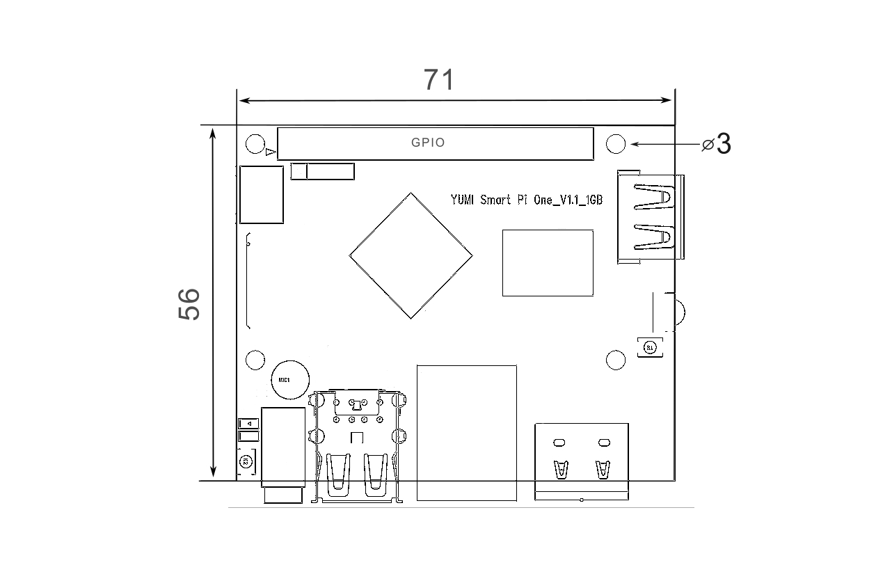
- PC Size: 72 mm x 60 mm
- Power Supply: DC 5V/2A or POWER DELIVERY CHARGER
- Working Temperature: -30℃ to 70℃
- Weight: 33g
- OS/Software: YumiOS, Debian 12(Armbian), Ubuntu(Armbian)
1.2 Software Features
Official Linux Server Image: https://wiki.yumi-lab.com/SmartPI/SmartPi_Linux/
1.3 Layout
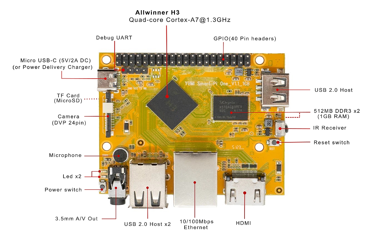
[Top view]
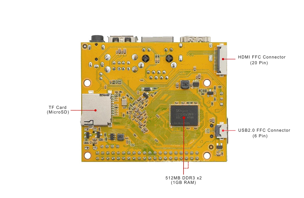
[Bottom view]
1.4 Diagram
GPIO Pin Spec

| Pin# | Name | Linux gpio | Pin# | Name | Linux gpio |
|---|---|---|---|---|---|
| 1 | SYS_3.3V | 2 | VDD_5V | ||
| 3 | I2C0_SDA/GPIOA12 | 4 | VDD_5V | ||
| 5 | I2C0_SCL/GPIOA11 | 6 | GND | ||
| 7 | GPIOG11 | 203 | 8 | UART1_TX/GPIOG6 | 198 |
| 9 | GND | 10 | UART1_RX/GPIOG7 | 199 | |
| 11 | UART2_TX/GPIOA0 | 0 | 12 | GPIOA6 | 6 |
| 13 | UART2_RTS/GPIOA2 | 2 | 14 | GND | |
| 15 | UART2_CTS/GPIOA3 | 3 | 16 | UART1_RTS/GPIOG8 | 200 |
| 17 | SYS_3.3V | 18 | UART1_CTS/GPIOG9 | 201 | |
| 19 | SPI0_MOSI/GPIOC0 | 64 | 20 | GND | |
| 21 | SPI0_MISO/GPIOC1 | 65 | 22 | UART2_RX/GPIOA1 | 1 |
| 23 | SPI0_CLK/GPIOC2 | 66 | 24 | SPI0_CS/GPIOC3 | 67 |
| 25 | GND | 26 | SPDIF-OUT/GPIOA17 | 17 | |
| 27 | I2C1_SDA/GPIOA19/PCM0_CLK/I2S0_BCK | 19 | 28 | I2C1_SCL/GPIOA18/PCM0_SYNC/I2S0_LRCK | 18 |
| 29 | GPIOA20/PCM0_DOUT/I2S0_SDOUT | 20 | 30 | GND | |
| 31 | GPIOA21/PCM0_DIN/I2S0_SDIN | 21 | 32 | GPIOA7 | 7 |
| 33 | GPIOA8 | 8 | 34 | GND | |
| 35 | UART3_CTS/SPI1_MISO/GPIOA16 | 16 | 36 | UART3_TX/SPI1_CS/GPIOA13 | 13 |
| 37 | GPIOA9 | 9 | 38 | UART3_RTS/SPI1_MOSI/GPIOA15 | 15 |
| 39 | GND | 40 | UART3_RX/SPI1_CLK/GPIOA14 | 14 |
Debug Port(UART0)
| Pin# | Name |
|---|---|
| 1 | GND |
| 2 | VDD_5V |
| 3 | UART_TXD0/GPIOA4 |
| 4 | UART_RXD0/GPIOA5/PWM0 |
DVP Camera IF Pin Spec
| Pin# | Name | Description |
|---|---|---|
| 1, 2 | SYS_3.3V | 3.3V power output, to camera modules |
| 7,9,13,15,24 | GND | Ground, 0V |
| 3 | I2C2_SCL | I2C Clock Signal |
| 4 | I2C2_SDA | I2C Data Signal |
| 5 | GPIOE15 | Regular GPIO, control signals output to camera modules |
| 6 | GPIOE14 | Regular GPIO, control signals output to camera modules |
| 8 | MCLK | Clock signals output to camera modules |
| 10 | NC | Not Connected |
| 11 | VSYNC | Vertical synchronization to CPU from camera modules |
| 12 | HREF/HSYNC | HREF/HSYNC signal to CPU from camera modules |
| 14 | PCLK | PCLK signal to CPU from camera modules |
| 16-23 | Data bit7-0 | Data signals |
1.5 Board Dimension
1.6 Case SmartPi One
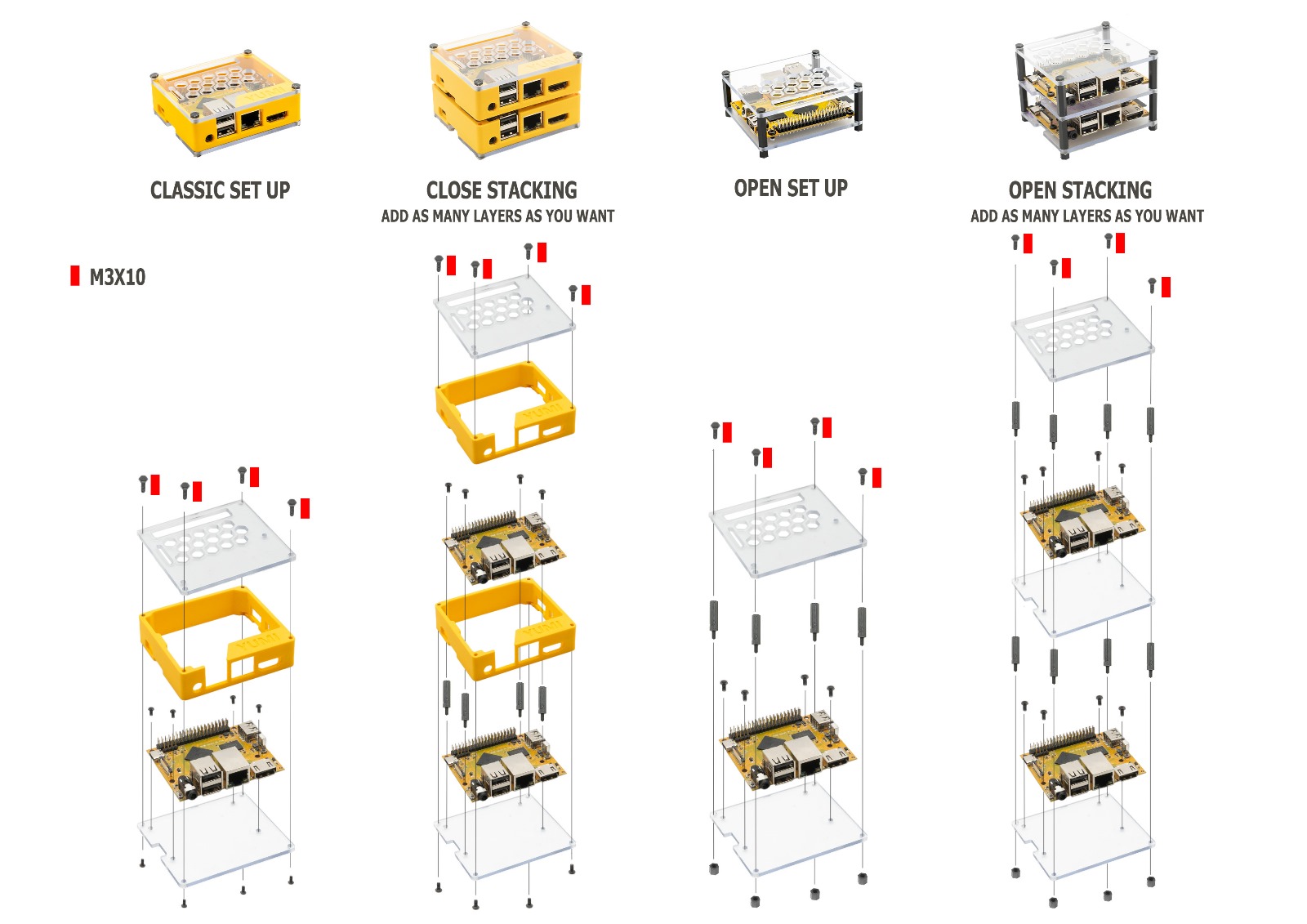
SmartPione Cases: Versatility and Style for Your Nano-Computer
Give your SmartPione the protection it deserves with our modular and versatile cases. Designed to suit various operational modes, these cases are an excellent solution to safeguard and showcase your electronic board while meeting the demands of your project.
Available Modes:
-
Classic Mounting: A simple and effective solution for standard use. This format perfectly protects the board while ensuring easy access to essential connectors.
-
Closed Stacking: Ideal for projects requiring multiple stacked boards. This mode provides excellent protection against dust and impacts while maintaining a compact and sleek design.
-
Open Simple Mode: Perfect for direct use or testing that requires easy access to electronic components and GPIO. A minimalist and practical solution for advanced users.
-
Open Stacking: Designed for multi-board setups where access to each level is essential. This mode is perfect for complex projects requiring optimal cooling or frequent manipulation of stacked boards.
Why Choose Our Cases?
- Optimal Protection: Safeguard your board from external elements like dust, shocks, or debris.
- Adaptable Design: Easily switch between modes to fit your operational needs.
- Aesthetic and Functional: Showcase your SmartPione while enhancing its practicality for various uses.
- Modularity: The different configurations perfectly suit your needs, whether it’s a prototype, a development project, or a final installation.
With our SmartPione cases, combine style, protection, and flexibility to unlock the full potential of your nano-computer.